Access control
Wiegand Wiring Diagram: Reader Wire Colors, Cable Distance and Common Faults
By Henrium · · 9 min read
Quick answer
A Wiegand reader needs four core connections: +V (usually 12 V DC), GND, D0 and D1, plus optional LED and buzzer control. Tie the reader and controller grounds together, use shielded stranded cable and check the voltage at the reader under load. Most faults on site come from swapped D0/D1, a missing common ground or a format mismatch.
Most Wiegand problems on site are wiring problems, not reader faults. A Wiegand reader needs only four core connections, but voltage drop, a missing ground or two swapped data lines can make a working reader look dead, or make it send numbers that never match the card.
This guide covers the standard connections and color codes, the wire maps of our wall readers, cable gauge and distance with voltage-drop math, and a fault table for commissioning. For the data format itself, see Wiegand 26 vs 34.
The wires on a Wiegand reader
| Function | Common color | What it does | Connect to |
|---|---|---|---|
| +V (power) | Red | Reader supply, usually 12 V DC | Controller reader-power output or a separate supply |
| GND | Black | Supply return and signal reference | Controller GND, always, even with a separate supply |
| D0 (Data 0) | Green | Pulses low for each 0 bit | Controller D0 / DATA0 |
| D1 (Data 1) | White | Pulses low for each 1 bit | Controller D1 / DATA1 |
| LED control | Varies (often orange, brown or grey) | Lets the controller switch the reader LED, e.g. green on access granted | Controller LED output (optional) |
| Buzzer control | Varies (often yellow) | Lets the controller sound the beeper | Controller buzzer output (optional) |
| Format select, hold, tamper | Varies | Model-specific functions | See the reader label |
| Shield / drain | Bare wire or foil | Cable screen | GND at the controller end only |
Red, black, green and white for power, ground, D0 and D1 is the most widely used convention, but it is not a rule. Some readers swap green and white, and LED and buzzer colors differ between brands. Always wire from the label or datasheet of the reader in your hand.
Wiring diagram: reader to controller
The basic connection, with the reader powered from the controller:
READER                         CONTROLLER READER PORT
Red     +12 V  ──────────────  +12 V (reader power)
Black   GND    ──────────────  GND
Green   D0     ──────────────  D0
White   D1     ──────────────  D1
LED     ctrl   ──────────────  LED output (optional)
Shield (drain) ──────────────  GND, controller end only
With a separate power supply near the reader, the grounds must still meet:
PSU +12 V ───────── Reader +V
PSU 0 V   ──┬────── Reader GND
            └────── Controller GND   (common ground, required)
Reader D0 / D1 ──── Controller D0 / D1
Without the common ground, D0 and D1 have no reference. The reader beeps and lights up on every card, but the controller sees nothing, or random bits.
Wire maps of our Wiegand readers
| Reader | Power | Ground | Wiegand data | Other connections | Supply |
|---|---|---|---|---|---|
| L410-W 125kHz Wiegand reader (also H410-W; D410-W availability confirmed in your quotation) | Red | Black | White and green: D0/D1 (assignment confirmed with your order) | Grey: green LED and buzzer control; purple: open = Wiegand 26, to GND = Wiegand 34 | 9–16 V DC, 0–100 mA |
| Q420-M slim QR + RFID reader | Red (12 V) | Black | Green: D0; white: D1 | Brown/orange: RS485 A/B; blue/yellow: RS232 RX/TX | 8–12 V DC, 800 mA |
| Q430-M QR + RFID reader, USB/RS485 | 12 V terminal | GND terminal | WG-D0 and WG-D1 terminals | 485-A/B, 232-RX/TX and TTL-RX/TX terminals | 8–12 V DC, 800 mA |
The L410-W has a 180 mm lead, so the joint to the site cable sits in the wall box or behind the reader. Crimp or solder it and insulate each conductor. The reader itself is resin-potted, so the joint is often the weakest point where moisture is present. The Q430-M has a 10-way terminal block in its rear box instead of flying leads.
Cable type, gauge and maximum distance
Use shielded, stranded, multi-conductor cable. 22 AWG is common for Wiegand runs. Six conductors cover power, ground, D0, D1, LED and buzzer; eight leave spares.
How far can it go? Our L410-W is specified for Wiegand runs of up to 100 m on shielded cable. You will often see about 150 m (500 ft) quoted in the industry for 22 AWG shielded cable. Treat any figure as conditional. The real limit is the voltage left at the reader and the noise picked up along the way, and both depend on your cable and route.
Rules that keep long runs reliable:
- Keep Wiegand cable away from mains, lighting circuits and lock power, and cross them at right angles where you must.
- Ground the shield at the controller end only. Grounding both ends can create a ground loop.
- Cat5e (24 AWG) or Cat6 (23–24 AWG) works on short runs, but its conductors have higher resistance than 22 AWG. Double up conductors for power and ground if you use it.
- For runs well beyond 100 m, or many readers on one cable, RS485 is the better interface. It is differential and is routinely run over hundreds of meters. See choosing an RFID reader interface.
Voltage drop: measure at the reader, not at the panel
Current flows out on the +V wire and back on GND, so the drop is across both conductors:
Voltage drop (V) = 2 × cable length (m) × conductor resistance (Ω/m) × current (A)
Copper conductor resistance is about 0.053 Ω/m for 22 AWG, 0.033 Ω/m for 20 AWG and 0.021 Ω/m for 18 AWG.
| Cable | Run length | Drop at 100 mA (L410-W maximum) | Drop at 800 mA (Q420-M / Q430-M rating) |
|---|---|---|---|
| 22 AWG | 50 m | 0.53 V | 4.24 V |
| 22 AWG | 100 m | 1.06 V | 8.48 V |
| 20 AWG | 50 m | 0.33 V | 2.64 V |
| 18 AWG | 50 m | 0.21 V | 1.68 V |
| 18 AWG | 100 m | 0.42 V | 3.36 V |
Two examples, starting from 12 V at the controller:
- L410-W on 100 m of 22 AWG: about 10.9 V at the reader, comfortably inside its 9–16 V range.
- Q420-M on 50 m of 22 AWG: at the full 800 mA rating, about 7.8 V at the reader, below its 8 V minimum. Use 18 AWG for power (about 10.3 V at the reader), or fit a local 12 V supply with a common ground. The real draw may be lower than the rating, but size the cable for the rating.
Also check that the controller’s reader output can deliver the current. Some reader ports are rated for less than the 800 mA a QR reader is specified for. UHF long-range readers need far more again: the U630-M 9 dBi integrated UHF reader is specified for a 12 V, 3 A supply, which calls for a dedicated supply at the pole.
LED, buzzer and format-select wires
Most controllers switch the reader LED or buzzer by pulling the control wire to GND through an output, so the reader turns green or beeps when access is granted. Check whether the controller output switches to GND (open collector) or drives a voltage. A mismatch here is a common reason the LED never changes color.
On the L410-W, the grey wire controls the green LED and the buzzer together, and the purple wire selects the format: leave it open for Wiegand 26, connect it to GND for Wiegand 34. Insulate unused wires one by one. A bare purple wire touching GND silently switches the reader to 34-bit.
Power, locks and grounding
- Keep lock power separate. Maglocks and electric strikes draw large currents and generate voltage spikes when they switch. Power them from their own supply, or at least their own fused output.
- Suppress the lock coil. Fit a diode across DC lock coils, or the suppressor the lock maker recommends. A reader that resets or beeps when the door releases is usually suffering from lock spikes.
- Use one ground reference. Reader, controller and any local supply share one 0 V. Do not bond it to earth at several points.
- Mind the mounting surface. Mounting directly on metal shortens read range. Offset entry and exit readers rather than mounting them exactly back-to-back, because adjacent readers can interfere, and test both with the doors closed.
Common Wiegand wiring faults and fixes
| Symptom | Likely cause | What to check |
|---|---|---|
| No LED, no beep | No power, reversed polarity or voltage too low | Measure +V to GND at the reader with a card present |
| Beeps, but the controller logs nothing | Open data line, no common ground, wrong reader port or format mismatch | D0/D1 continuity, the GND link, the controller’s format setting |
| Beeps, controller reports a parity error or invalid card | D0 and D1 swapped | Swap the two data wires |
| The same wrong number every time | Format or display mismatch (26 vs 34, facility + card vs full decimal) or byte order | Compare with the Wiegand 26/34 calculator |
| Some reads missed, some wrong | Noise: unshielded cable beside mains, or shield grounded at both ends | Re-route the cable; ground the shield at one end only |
| Reader resets when the lock fires | Shared supply, no lock suppression | Separate the lock supply; add a diode |
| Works on the bench, fails on site | Voltage drop on the long run | Measure the voltage at the reader under load |
| Short read range | Metal mounting, low voltage or a nearby reader | Non-metal spacer, supply voltage, reader spacing |
Why do swapped data lines usually give an error rather than a wrong number? Swapping D0 and D1 inverts every bit. In a 26-bit frame, the first parity group (bits 1–13) has an odd number of bits, so inverting it always breaks the even parity. The same happens with the 17-bit groups of a 34-bit frame. A controller that checks parity rejects every read. One that ignores parity logs the bitwise inverse of the real number.
A multimeter answers most questions. With no card present, D0 and D1 should each sit at the idle-high level against GND, typically around 5 V, depending on the controller. A line at 0 V is shorted or has no pull-up. The data pulses themselves are too short for a multimeter to show; to confirm that a frame leaves the reader, put an oscilloscope or logic analyzer on D0 and D1, or watch the controller’s event or diagnostic log.
Installation checklist
- Read the reader label and the controller manual; note both wire maps and the Wiegand format.
- Choose shielded, stranded cable and size the power conductors with the voltage-drop formula.
- Route the cable away from mains and lock power, and leave a service loop at the reader.
- Connect +V, GND, D0 and D1, then LED and buzzer control if used. Insulate every unused wire.
- Tie all grounds together and ground the shield at the controller only.
- Set the format at both ends (on the L410-W, purple wire open or to GND).
- Measure the voltage at the reader with a card present.
- Present a known card and compare the logged number with the printed one, or with the number a USB card enrollment reader types at the desk.
- Operate the lock with the reader running to confirm it does not reset.
- Keep the controller and cable on the secure side of the door and fix the reader with tamper-resistant screws. Wiegand is unencrypted, so the cable should not be reachable from outside.
Commissioning goes faster when the reader already matches the controller. Order a sample reader preset to your controller’s Wiegand 26 or 34 format, and bench-test it with the controller and a few site cards before the installation day.
To compare our wall readers, see the Wiegand 26/34 access control readers and the QR code + RFID access readers; for serial alternatives, see the RS232 and RS485 readers. If a reader still does not read after these checks, work through RFID reader not reading cards.
Frequently asked questions
What are the standard Wiegand wire colors?
The most common convention is red for +V, black for GND, green for D0 and white for D1. LED and buzzer control wires vary by brand, and some readers swap green and white, so always wire from the label on the reader you are installing. On the L410-W, the white/green D0/D1 assignment is confirmed with your order.
How far can a Wiegand reader be from the controller?
Our L410-W is specified for up to 100 m of shielded cable. About 150 m (500 ft) on 22 AWG shielded cable is often quoted in the industry, but the real limit is the voltage left at the reader and the noise picked up along the route. For much longer runs, a reader with RS485 output is the better choice.
What happens if D0 and D1 are swapped?
Every bit is inverted. Because each parity group in a 26-bit or 34-bit frame has an odd number of bits, inversion always breaks the parity, so a controller that checks parity rejects every read. A controller that ignores parity logs the bitwise inverse of the real number. Swap the two data wires to fix it.
Can I power a Wiegand reader from a separate power supply?
Yes, and it is often necessary for long runs or for QR readers rated at 800 mA. Connect the supply's 0 V to both the reader GND and the controller GND. Without that common ground the data lines have no reference, and the controller sees nothing or random bits.
Do I need shielded cable for Wiegand?
It is strongly recommended. Use shielded, stranded, multi-conductor cable, keep it away from mains and lock power, and connect the shield to GND at the controller end only. Grounding the shield at both ends can create a ground loop.
Readers mentioned in this guide
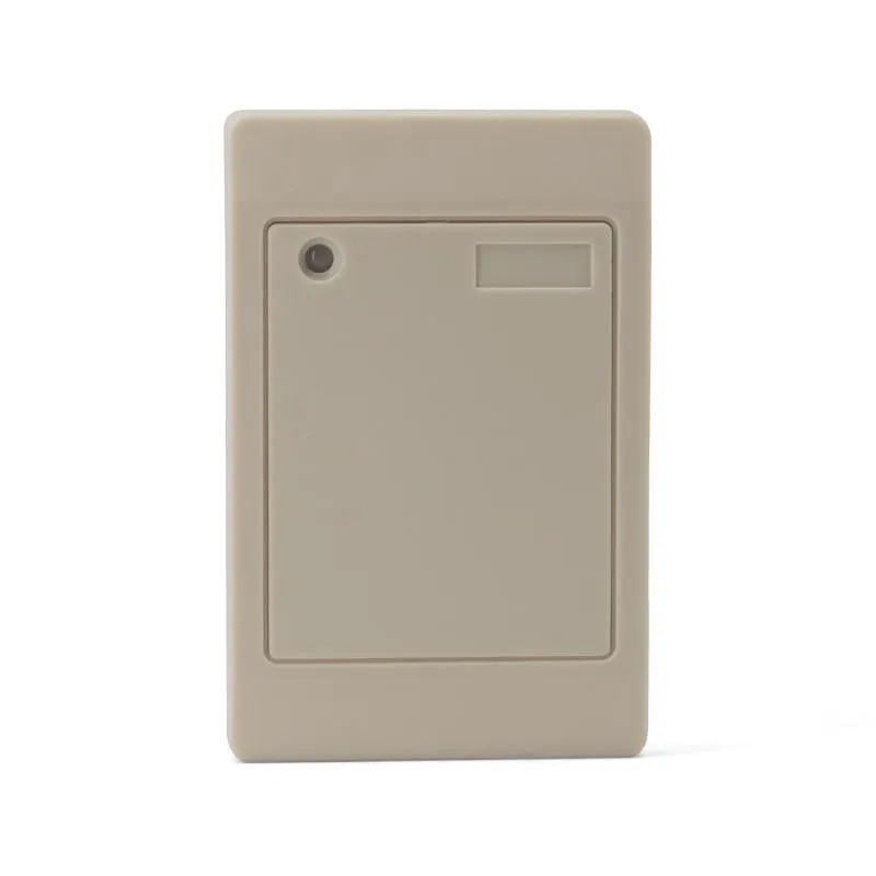 125kHz
 L410-W+2 variants
Waterproof 125kHz Wiegand 26/34 RFID Access Reader, Resin-Potted
- Wiegand
- Wall-mount
Read range: 0–100 mm
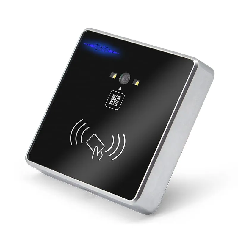 QR + RFID
 Q420-M
QR Code + RFID Access Reader, Wiegand 26/34, RS485, Slim 86-Box
- RS232
- RS485
- Wiegand
- Wall-mount
Read range: 3–6 cm
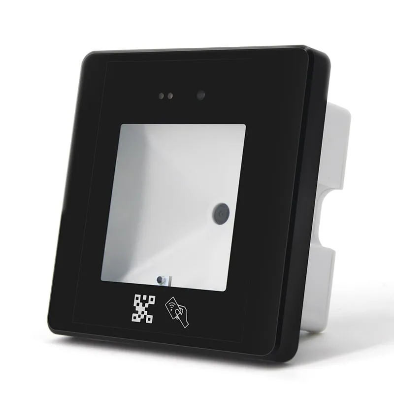 QR + RFID
 Q430-M
QR Code + RFID Access Reader with USB, Wiegand and RS485, 86-Box
- USB
- RS232
- RS485
- Wall-mount
Read range: 3–6 cm