UHF RFID
UHF RFID Read Range: Why One Reader Reads 0.5 m and Another 20 m
By Henrium · · 10 min read
Quick answer
UHF RFID read range depends on how much reader power reaches the tag chip. That depends on radiated power (EIRP), capped at 4 W EIRP in the US and 2 W ERP in the EU, on the tag's chip and antenna, and on what the tag is mounted on. Desktop readers are built for 0.5 m, gate readers for meters.
A datasheet that says “read range up to 12 m” describes one tag, one power setting and one test site. Put a different tag on a metal box, mount the reader beside a steel wall or turn the power down to meet local rules, and the same reader may stop at 3 m.
This guide explains what sets the distance between a UHF reader and a passive EPC Gen2 (ISO/IEC 18000-63) tag, using the numbers an RF engineer uses. It lists the rated ranges of our UHF readers side by side and ends with a field test to run before you fix a mounting position.
The short answer
- Range is a power budget. A passive UHF tag has no battery. It wakes up only when enough of the reader’s energy reaches its chip, then answers by reflecting part of that energy back (backscatter). In many systems, powering the tag is the limit, not hearing its reply.
- Four things set the budget: the reader’s radiated power, the tag’s chip and antenna, what the tag is attached to, and the site around it.
- National rules cap radiated power, at 4 W EIRP in the US and 2 W ERP in the EU. At the cap, more antenna gain gives a narrower beam, not more legal reach.
- Rated ranges are best cases. Use them to compare reader types, then confirm the distance with your own tags on your own items.
Rated read range by reader type
UHF reader types differ in range by a factor of 100 or more. That is a design choice, not a quality ranking: a desk encoder that read 10 m would pick up every tag in the office. Rated ranges from our product specifications:
| Reader type | Our models | Antenna, RF power | Rated read range |
|---|---|---|---|
| USB-C plug-in for Android phones | U220-C USB-C UHF reader | Not stated | 0–5 cm |
| Ring-antenna handheld with display | U520-M | Not stated | 0–35 cm |
| Pocket Bluetooth reader | U510-B | Not stated | 0–50 cm |
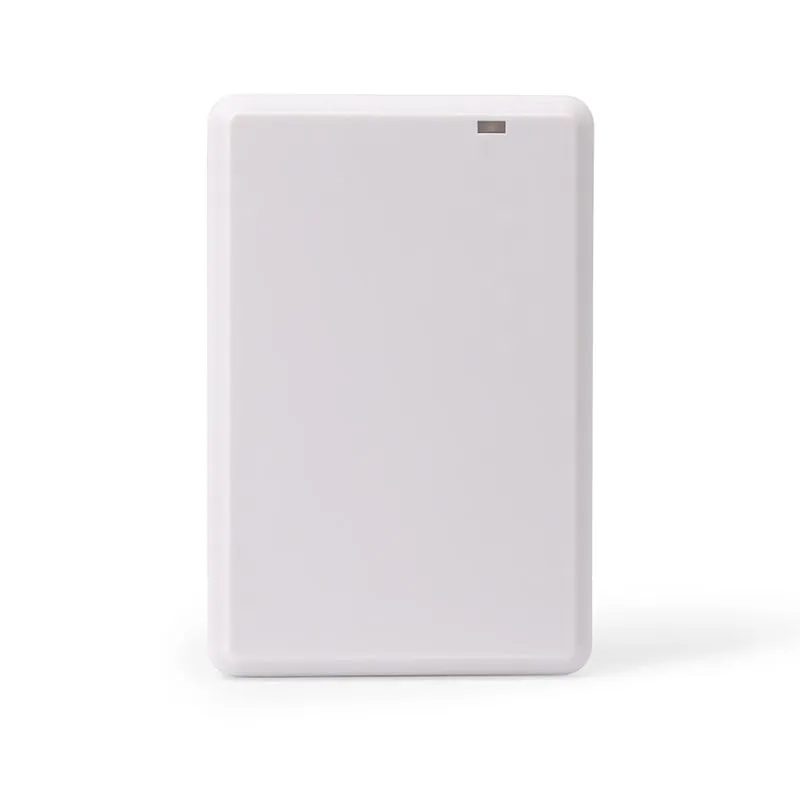
| USB desktop reader/writer | U120-U, U130-U, U140-U, U160-U | 2 dBi, 12.5–26 dBm | Read 0.5 m, write 0.2 m |
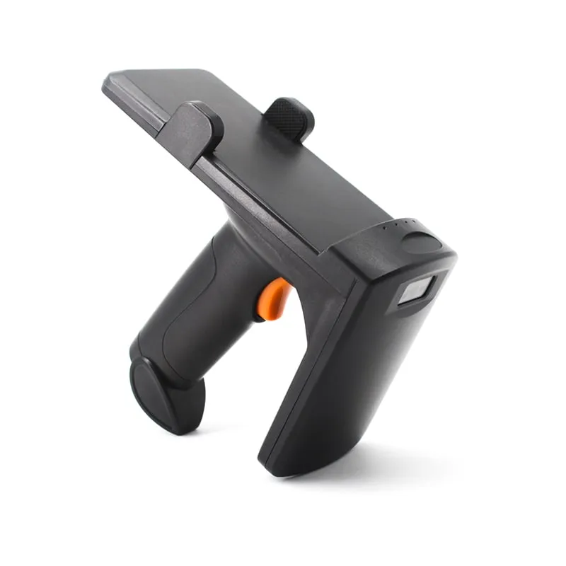
| Pistol-grip handheld | U550-M | Not stated | 0–3 m |
| Integrated reader | U610-M | 7 dBi, 0–30 dBm | 0–5 m (8 m high-power) |
| Integrated reader | U620-M | 8 dBi, 0–30 dBm | 0–5 m (8 m high-power) |
| Integrated reader | U630-M | 9 dBi, 0–30 dBm | 0–6 m (10 m high-power) |
| Integrated reader | U640-M 10 dBi long-range UHF reader | 10 dBi, 0–30 dBm | Stable beyond 12 m |
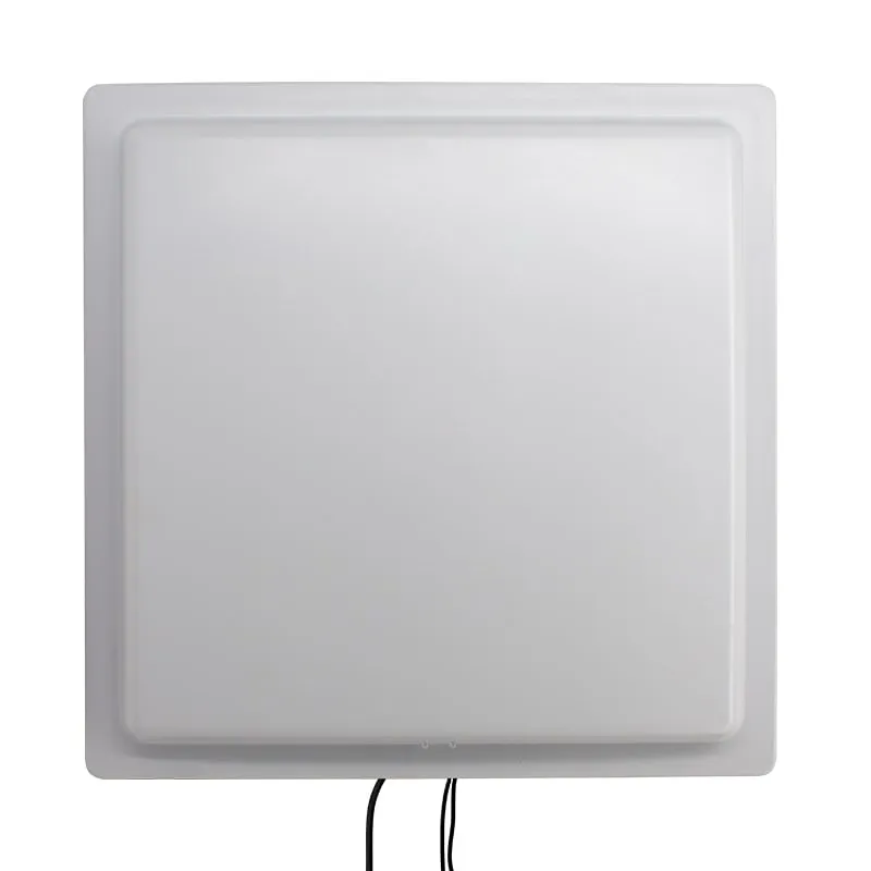
| Integrated reader | U650-M 12 dBi long-range UHF reader | 12 dBi, 0–30 dBm | 0–20 m (35 m high-power) |
All of these depend on the tag and the site, and our specifications do not state which tag or power setting produced them. At the full 30 dBm, even the 7 dBi U610-M radiates 37 dBm EIRP, above the 4 W (36 dBm) US limit. Treat every integrated-reader figure, and the high-power figures in particular, as a best case, and expect less at a legal power setting; the section on the legal cap below shows why.
The U540-M UHF and barcode handheld is left out of this table because its range figure has not yet been confirmed by test, so measure it with your own tags. For comparison, our 125 kHz and 13.56 MHz desktop readers read cards at up to 80 mm, because those bands use near-field magnetic coupling, which fades quickly with distance. All UHF models are on the UHF RFID readers page.
How the power budget sets range
RF engineers work in decibels because gains and losses then simply add up. Three terms explain any range claim:
- EIRP (equivalent isotropically radiated power) is the reader’s conducted output plus antenna gain, minus cable loss. A reader at 30 dBm (1 W) into a 6 dBi antenna radiates 36 dBm EIRP (4 W). ERP, used in European rules, is referenced to a dipole instead: EIRP = ERP + 2.15 dB.
- Path loss in free space is about 31.7 dB at 1 m at 915 MHz and grows by 6 dB each time the distance doubles.
- Chip sensitivity is the lowest power at which a tag chip still answers. EPC Gen2 chips list read sensitivities from about −18 dBm for older designs to about −25 dBm for recent ones; the figure varies by chip vendor.
A worked example for the forward link at 915 MHz in free space, with illustrative values:
| Step | Value |
|---|---|
| Reader EIRP at the US limit | +36 dBm |
| Path loss at 10 m | −51.7 dB |
| Tag antenna gain (typical label inlay) | +1 dBi |
| Polarization loss (circular reader antenna, linear tag) | −3 dB |
| Power arriving at the chip | −17.7 dBm |
| Chip read sensitivity (example) | −20 dBm |
| Margin | 2.3 dB: the free-space limit is about 13 m |
Real sites are not free space. If the mounting surface or an awkward angle costs another 10 dB, the same tag stops answering at about 4 m. This conversion is the quickest way to judge a spec sheet or a site problem:
| Change in the power budget | +6 dB | +3 dB | −3 dB | −6 dB | −10 dB | −20 dB |
|---|---|---|---|---|---|---|
| Free-space range becomes | ×2 | ×1.4 | ×0.7 | ×0.5 | ×0.3 | ×0.1 |
The tag’s reply makes the same trip in reverse, so the reader’s receive sensitivity also counts. With today’s sensitive tag chips, a reader with a small antenna or a noisy receiver can reach its limit before the tag does.
Reader side: power, antenna gain, polarization, cable
RF output power is the setting you adjust on site: 12.5 to 26 dBm on our desktop reader/writers and 0 to 30 dBm on the integrated readers, both set in software. Lowering it is the normal way to keep a read zone inside a doorway, or away from tags waiting on a desk.
Antenna gain concentrates energy into a narrower beam. Because an antenna works the same way on receive, it also helps the reader hear weak tag replies. The cost is a narrower zone: a high-gain panel sees far down a lane but little to the sides.
The legal cap changes the picture. US rules (FCC Part 15.247) allow 1 W conducted into an antenna of up to 6 dBi; above 6 dBi, conducted power drops 1 dB for every extra dB of gain. The EU limit of 2 W ERP is about 35.2 dBm EIRP. From the stated antenna gain, with no cable loss and rounded down, the highest legal conducted setting is:
| Antenna gain | 2 dBi | 7 dBi | 8 dBi | 9 dBi | 10 dBi | 12 dBi |
|---|---|---|---|---|---|---|
| 4 W EIRP (US) | Not reached (26 dBm max) | 29 dBm | 28 dBm | 27 dBm | 26 dBm | 24 dBm |
| 2 W ERP (EU) | Not reached (26 dBm max) | 28 dBm | 27 dBm | 26 dBm | 25 dBm | 23 dBm |
So at the legal limit, a 12 dBi reader sends the tag no more power than a 7 dBi reader. Both radiate the same EIRP, one in a tighter beam. The extra gain still buys better receive sensitivity, a better-defined zone and less energy spilled toward neighboring lanes. A range measured at full 30 dBm into a high-gain antenna may not be legal where you install, so set power to keep EIRP within your local limit. Limits by country are in UHF RFID frequency bands by country.
Polarization. Most label tags are linearly polarized. A linear reader antenna reads farthest when the tag lines up with it and hardly at all when the tag is turned 90°. A circularly polarized antenna reads the tag at any rotation in the plane facing it, at a cost of about 3 dB. Our desktop reader/writers use a circularly polarized 2 dBi antenna.
Cable loss. A fixed reader with separate antennas loses power in every meter of coax; thin RG-58-type cable loses roughly 0.5 dB per meter or more at 900 MHz. Integrated readers avoid this because the antenna sits in the reader housing.
Tag side: chip, antenna size, band and writing
- Chip sensitivity. A chip that needs 3 dB less power reads about 1.4 times as far in free space when powering the tag is the limit.
- Antenna size. Half a wavelength is about 16 cm at 915 MHz and 17 cm at 866 MHz. Label inlays that approach that length read farthest; small tags for tools, jewelry or laundry trade range for size, sometimes to well under a meter.
- Band tuning. Tag antennas are tuned. A tag optimized for 902–928 MHz can read noticeably shorter with an 865–868 MHz reader, and the reverse. “Global” tags give up a little peak performance to cover both.
- Read vs write. Writing EPC or user memory needs more power at the chip than answering a read, so write range is shorter: our desktop units read at up to 0.5 m and write at up to 0.2 m. Encode one tag at a time with other tags kept out of the field, and lower the power only as far as that requires; see how to write UHF tags.
Mounting surface, orientation and site effects
| Condition | What happens | What to do |
|---|---|---|
| Standard label on metal | The tag antenna detunes; a label directly on steel may not read at all | Use on-metal tags or a spacer |
| Liquid-filled items | Water absorbs UHF energy | Use tags made for liquids; mount near the neck or cap, or over an air gap |
| Badges worn on the body | The body absorbs energy and shields the tag | Expect shorter range; test with people walking through |
| Tag pointing end-on at the antenna | A dipole tag receives almost nothing along its own axis | Fix the tag orientation, or use a circularly polarized antenna |
| Coated windshields | Some athermic or metal-coated glass blocks UHF | Use the uncoated area or a headlamp tag; see parking and vehicle access |
| Metal walls, vehicles, racking | Reflections create dead spots and hot spots | Tilt or move the reader, reduce power, use the trigger input |
| Other readers nearby | Readers interfere with each other | Separate channels and read timing; reduce power |
| Moving tags | At 20 km/h a vehicle crosses a 4 m zone in about 0.7 s | Size the zone for speed and tag count; see multi-tag read rates |
Choose the range you need, not the longest
Too much range causes as many problems as too little. At a desk it reads the next tag in the pile; at a gate it opens the barrier for the car in the queue. Measure from the mounting point to the farthest position you must read and the nearest position you must not. Then pick the reader type that covers the first with margin: a desk unit (up to 0.5 m), a handheld (centimeters to 3 m) or an integrated long-range reader (meters). Among integrated readers, the U610-M (7 dBi) and U630-M (9 dBi) suit single lanes and doorways. The U640-M (10 dBi) and U650-M (12 dBi) suit readers set back from the lane, where the narrower beam keeps the zone tight and the extra gain helps the reader hear weak tag replies, even at the same legal EIRP. Trim RF power on site until the far edge reads reliably and the no-read positions stay quiet. The trade-offs between reader types are covered in fixed vs integrated vs handheld UHF readers.
Field test checklist
- Use your real tags on real items, including the worst case: on metal, on a full bottle, behind your most common windshield.
- Set the reader up as it will run: the country’s band, an RF power that keeps EIRP legal, the final height and tilt.
- Record read rate, not maximum distance. Pass each item through the zone 20 times at each distance and note the percentage read.
- Step the distance in 0.5 m increments; dead spots show up as failures closer in than the maximum.
- Test every orientation the tag can take in normal use.
- Test at working speed, with people, vehicles or forklifts moving as they will in operation, and with neighboring readers running.
- Keep a margin. Plan on 3–6 dB, which means designing the zone for 50–70% of the distance that read reliably.
To run this test before a volume order, request sample readers and send your tag type and site layout through the contact page.
Frequently asked questions
What is the maximum read range of a passive UHF RFID tag?
It depends on the tag, the legal power limit and the site. In open space at the legal limits, large label tags with sensitive chips can read beyond 10 m. On real items, especially near metal, liquids or people, a few meters is more typical. Our integrated readers are rated from 0–5 m (7 dBi) to 0–20 m (12 dBi), depending on tag, site and power setting.
Does a higher-gain antenna always increase UHF read range?
Only while the reader stays below the legal radiated power limit. EIRP is conducted power plus antenna gain, and the limit applies to the total. With a 12 dBi antenna, a reader has to run at about 24 dBm to stay within 4 W EIRP in the US. Above that point, extra gain narrows the beam and improves receive sensitivity, but it does not send more power to the tag.
Why is UHF write range shorter than read range?
A passive tag needs more power at its chip to write memory than to answer a read, so writing only works closer to the antenna. Our USB desktop reader/writers read at up to 0.5 m and write at up to 0.2 m. Encode one tag at a time, close to the pad, and keep other tags out of the field so the write reaches only the tag you mean to change.
Why does a UHF tag read at 6 m but not at 4 m?
Reflections from metal, floors and vehicles add to or cancel the direct signal, which creates dead spots and hot spots at fixed points in the read zone. Moving the tag a few centimeters, tilting the reader or changing its height usually moves the dead spot. Test at several distances, not only at the maximum.
How do I make a UHF reader read a shorter distance?
Lower the RF output power in software, choose a lower-gain reader, tilt the reader down toward the read zone, or use a trigger input so the reader reads only when a vehicle or item is in position. Our integrated readers adjust RF power from 0 to 30 dBm and have one trigger input.
Readers mentioned in this guide
 UHF
UHF  UHF
UHF U610-M+1 variant
UHF Integrated RFID Reader, 7 dBi, 0–5 m, Wiegand/RS485/USB
- USB
- RS232
- RS485
- Fixed / long-range
Read range: 0–5 m
 UHF
UHF U650-M+1 variant
12 dBi Long-Range UHF RFID Reader, 0–20 m, Wiegand/RS485/TCP/IP
- USB
- RS232
- RS485
- Fixed / long-range
Read range: 0–20 m
 UHF
UHF U550-M
Bluetooth UHF RFID Pistol-Grip Reader with Phone Holder
- USB
- Wireless
- Handheld
Read range: 0–3 m